Projects / 04 · Mechatronics course project
Digital Line-Following Robot
A small robot that follows a black line on the floor, built by three of us for the Mechatronics course at UNS. I managed the project and led the mechanical design, from the first concept to the CAD chassis the team built and tested.
- MY ROLE
- Project Manager & Design Lead
- SCHEDULE
- May — June 2025
- TEAM
- Three students
- BUILT WITH
- Arduino Uno · L298N · LED–LDR sensors
01
What we built, and who did what
Four LED and light-sensor pairs across the front shine on the floor and measure how much light comes back. A black line reflects less than the floor around it. An Arduino Uno reads the four sensors and tells an L298N motor driver how fast to turn each of the two geared DC motors. Speeding one wheel up and slowing the other steers the robot back over the line. Two 18650 cells power everything.
All three of us integrated and tested the robot together.
02 · MY WORK
Designing the chassis
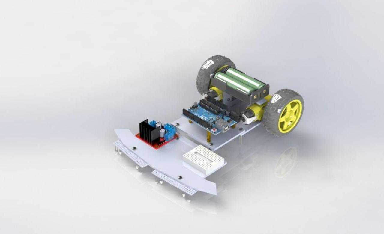
I worked from the parts list outwards: everything had to fit, stay reachable for wiring and keep the sensors in the right place. I started with hand sketches, moved into 3D CAD, checked dimensions and placement against the actual components, reviewed the layout with the team, and then finalised it.
The result is a small layered chassis. Two laser-cut plates in the middle carry the Arduino and motor driver, joined with M3 standoffs. The motors and 65 mm wheels sit at the back, with the battery pack in a 3D-printed rear housing between them, and a ball caster gives the third point of contact. At the front, an acrylic mount holds the sensor boards about 8 mm above the floor, so every sensor sees the track from the same height.
03
From CAD to a working robot
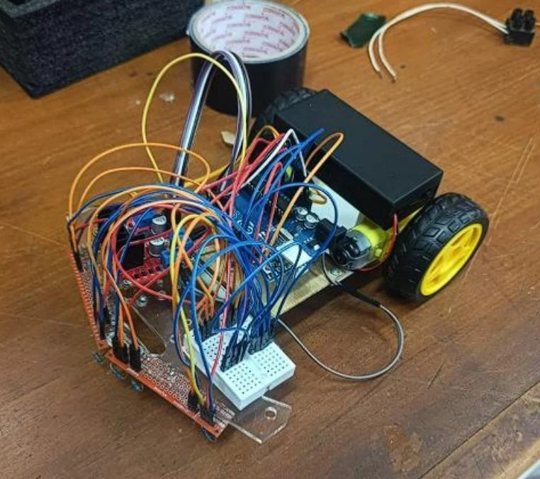
Vidy cut the frame parts and assembled the chassis, and Kevin soldered the sensor circuits onto perfboard and wired everything to the Arduino. As the build came together, a few things changed from the first wiring plan. The motor driver became a frame-mounted L298N module instead of a chip on a breadboard. The sensors went onto soldered boards rather than a breadboard. A pair of rechargeable 18650 cells replaced a 9 V battery.
The photo at the top shows the honest version. The layout follows the CAD, but the real robot carries a lot of jumper wiring the model never had to show.
Fabrication and assembly photos from the project report. Team build.
04
On the track
We ran four timed trials on the test track. The robot followed sections of the track, but not smoothly: it oscillated around the line and lost it, particularly at changes of direction. It didn’t complete the full course in any of the four trials. Each run ended at checkpoint 4 or 5.
| Trial | Stopped at checkpoint | Recorded time |
|---|---|---|
| 1 | 4 | 8.19 s |
| 2 | 4 | 8.12 s |
| 3 | 5 | 10.18 s |
| 4 | 5 | 10.07 s |
From the report’s summary table. Each time runs only to the checkpoint where that trial ended, so none is a complete-course time, and the runs aren’t a like-for-like comparison.
In our report, we traced the oscillation to unsteady sensor readings, which made a fixed light threshold hard to set. Likely contributors were flickering lab lighting, LED brightness dropping as the battery ran down, small resistor differences between sensors, and vibration. We identified a regulated LED supply, a quick calibration before each run, infrared sensors and PID steering as ways to improve sensor stability and control in further development. They weren’t built into this prototype.
05
Where it ended up
We finished with a functioning physical robot that followed sections of the track, though not the full course, built in about six weeks on a budget of Rp 394,800. For me, the project meant taking a design from my CAD model all the way to something built and tested, and keeping three people’s work lined up through weekly meetings along the way.