Projects / 05 · Machine Elements design project
Folding Skateboard
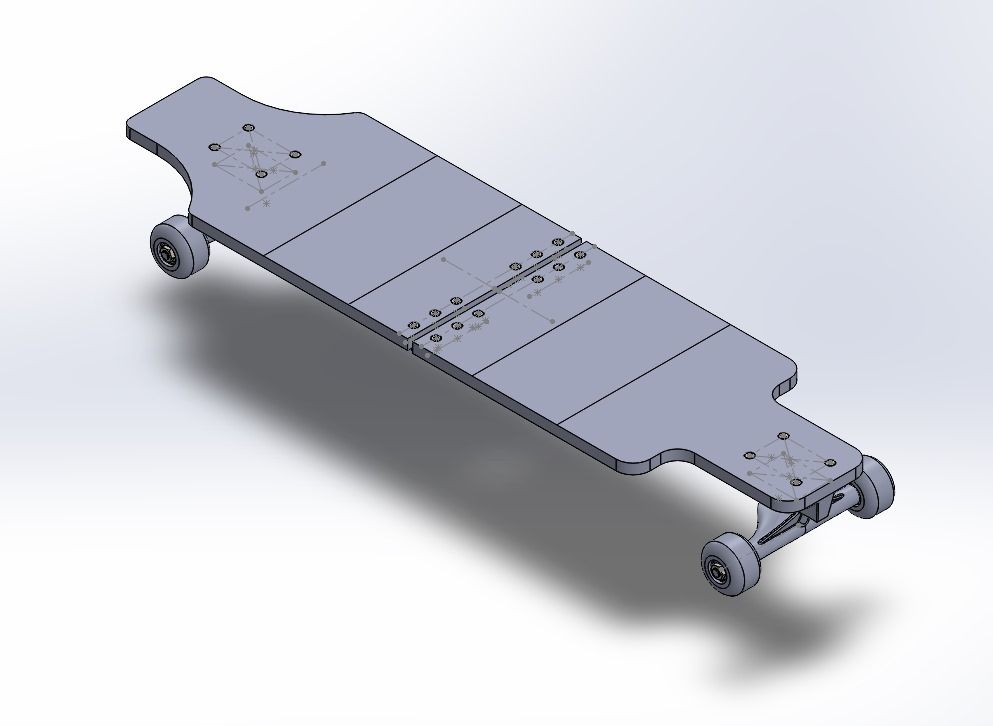
A longboard-style skateboard that folds in half at a central hinge, so it’s easier to carry and store. Three of us took the idea from concept through CAD, material choices, strength calculations and a static simulation for our Machine Elements course.
- COURSE
- Machine Elements · UNS · 2024
- TEAM
- Steven Ericson Simamora, Kevin William Markus Simbolon and me
- TOOLS
- SolidWorks · hand calculations
- DELIVERABLES
- CAD design, drawings, calculations, simulation
01
The idea
A skateboard is long and rigid, which makes it awkward to carry on public transport or store in a small space. Our brief to ourselves was to make one that folds in half, without giving up the strength and stability a rider relies on, and with a folding action that stays simple.
02
Designing the fold
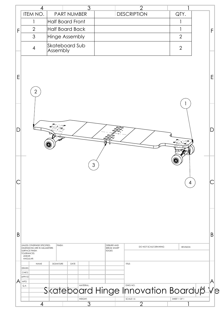
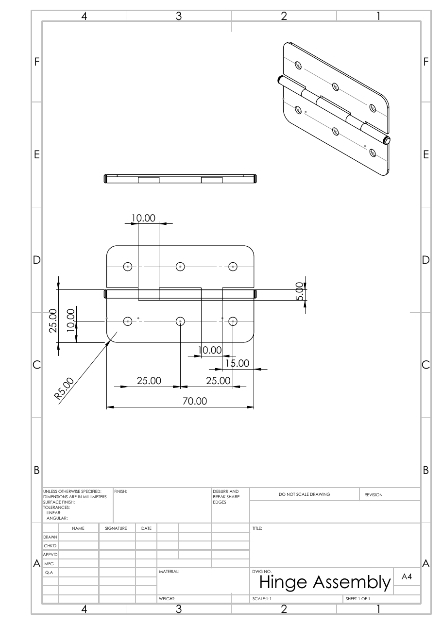
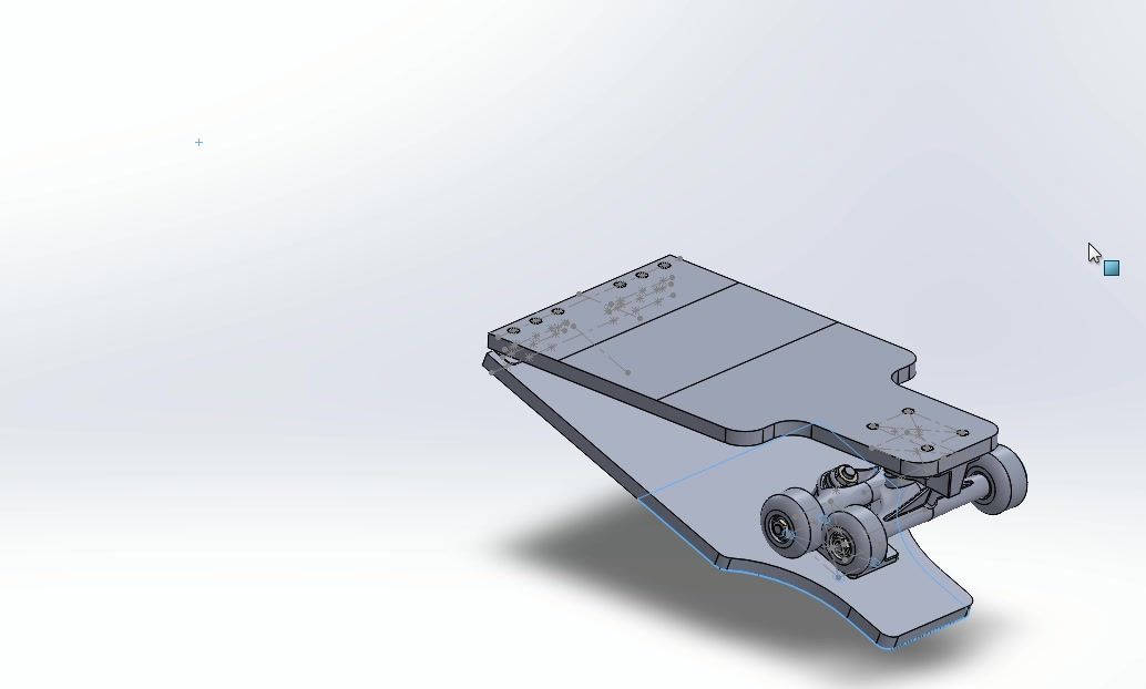
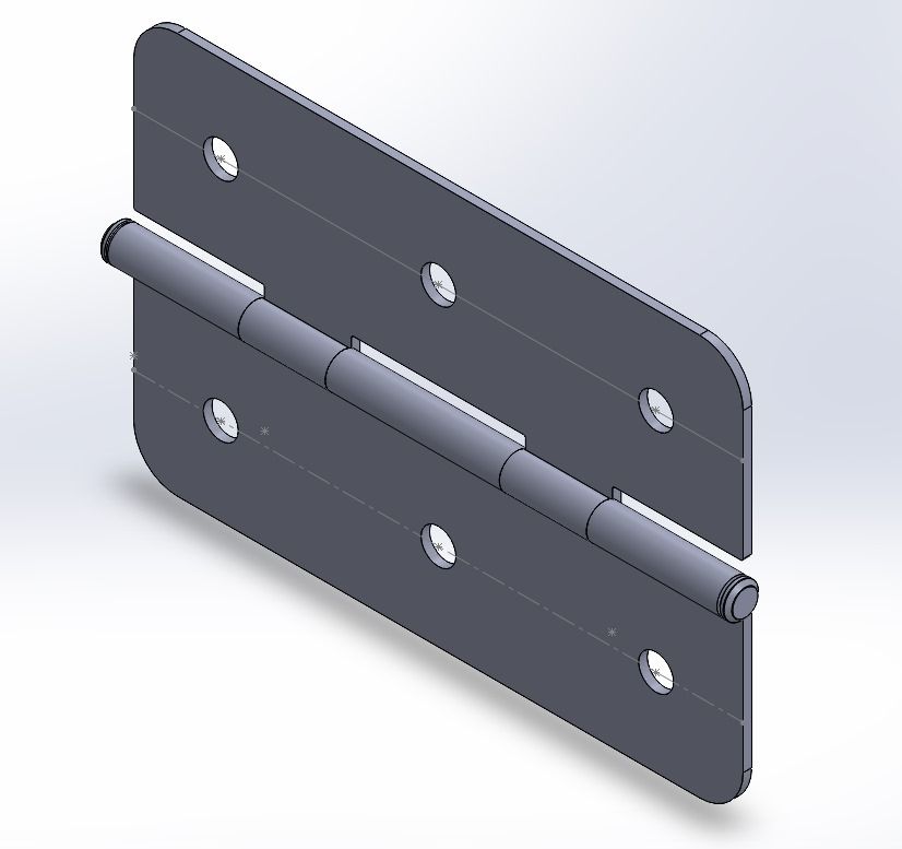
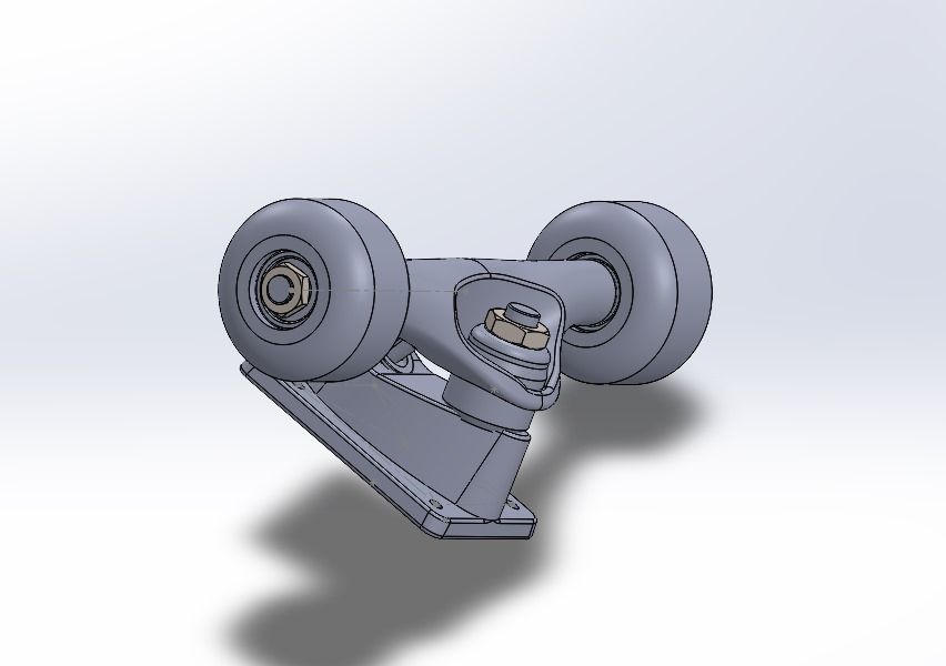
We split an 840 mm deck into a front half and a back half, each carrying its own truck and pair of wheels at the outer end. A pair of stainless-steel hinges, bolted across the joint at the middle, connect the two halves. Unfolded, the board rides as one piece on trucks 625 mm apart. Folded, the halves swing together around the hinge line and the board roughly halves in length.
03
Materials and calculations
We chose a material for each part based on what it has to do: a light, water-resistant deck, corrosion-resistant hardware, and strong metal where the loads concentrate.
| Deck halves | Rigid PVC |
|---|---|
| Hinges, bolts and nuts | AISI 316L stainless steel |
| Trucks | Cast carbon steel |
| Wheel shaft | AISI 4340 steel, normalised |
| Wheels | Nylon |
For the strength checks we used a 100 kg rider as the design load. We modelled the deck as a beam on the two trucks, with the hinge at mid-span, and drew its free-body, shear and bending-moment diagrams. From there we checked three parts by hand: tension in the 4 mm bolts and the bolt loads at the front and rear deck joints, bending and shear in the wheel shaft against the Tresca and von Mises criteria, and the bending strength of the deck.
The report concluded that each of those parts stayed within its material’s limits. These were simplified, one-part-at-a-time hand calculations. They show how each part was checked, not that the assembled board is safe to ride.
04
What we produced
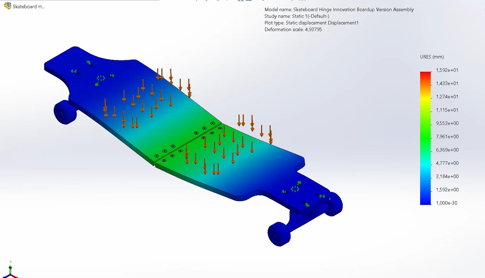
The project ended as a complete design package rather than a physical board: the full CAD assembly with its folding animation, a drawing set covering the assembly, hinge, truck parts and wheels, the hand calculations and the static simulation. Building and testing a real board would be the step that shows how the hinge joint, where the simulation showed the most deflection, holds up in use.