Projects / 01
Urban Air Mobility Aircraft
An electric air taxi designed by an eight-person student team from three universities. Within it I worked on the tilt-rotor mechanism, the part that swings each propeller between lifting the aircraft straight up and pulling it forward, and did most of that mechanism’s mechanical analysis.
- PROGRAMME
- Global Multidisciplinary Design Course (GMDC) · AEE 468
- TEAM
- Javan Aviation, Team 5 · ASU, ITB, UNS
- MY WORKSTREAM
- Tilt-rotor mechanism, shared with Samuel Louis Fajar Hasibuan
- WHEN
- Jan — May 2025
01
The aircraft and the brief
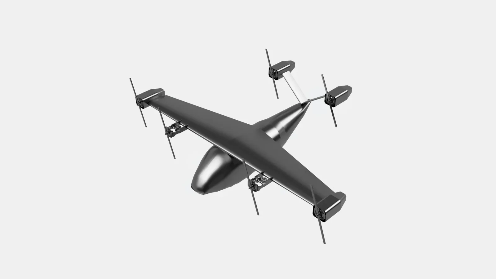
The brief asked for an electric aircraft to carry a pilot and six passengers within and between cities. It had to take off vertically from a small pad, cruise fast like a conventional plane, and recharge between flights in under twenty minutes. Our answer was a high-wing, V-tail design with six electric motors whose propellers tilt between hover and cruise.
Design requirements from the course brief, not measured performance.
02
An international team
GMDC put students from Arizona State University in the same team as students from two Indonesian universities, and each of us owned a workstream. The aircraft itself, from its configuration and sizing to its aerodynamics, structure and propulsion, was the team’s work as a whole.
| Workstream | University |
|---|---|
| Team leader | ASU |
| Aerodynamics, stability & control | ASU |
| Structures (×2) | ASU · ITB |
| Propulsion | ASU |
| Weight & balance | ITB |
| Tilt-rotor mechanism — Samuel Louis Fajar Hasibuan and me | UNS |
03
Where my part fits
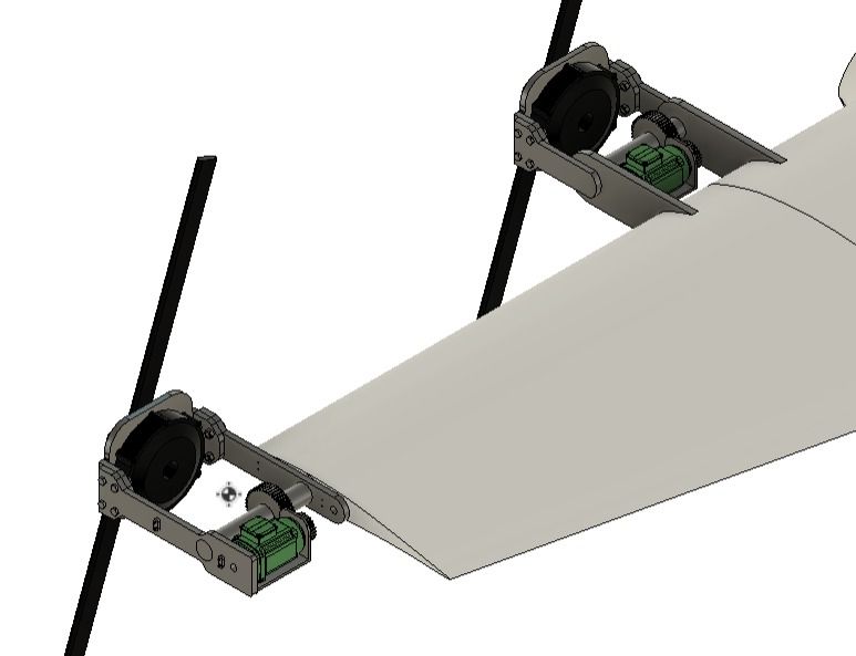
To hover, the propellers point up. To cruise, they point forward. Something has to rotate each motor nacelle between those positions while the propeller keeps running, and designing that mechanism was the job Samuel and I were given.
It couldn’t be done in isolation. Wing geometry, the space around the nacelle and the motor data all came from other workstreams, so I coordinated with them to make sure our subsystem was working from the right inputs and constraints.
04
Choosing a mechanism
Samuel and I each researched how a rotor could be tilted, then compared what we had found. We settled on a pair of spur gears. They’re well understood and straightforward to calculate and design, and the ratio can be changed simply by changing tooth counts. Our first evaluation suggested a 2:1 ratio would suit the job, so that’s what we used.
After that the work divided fairly naturally:
05
How the mechanism works
The larger gear stays fixed relative to the wing. A smaller pinion meshes with it from the outside and travels with the nacelle. When an electric actuator turns the pinion, the pinion walks around the fixed gear and carries the nacelle through its tilt.
Because the pinion travels around the gear instead of spinning in place, it behaves like a simple epicyclic arrangement. So the 2:1 tooth ratio isn’t the same thing as a 2:1 speed ratio between actuator and nacelle.
Requirement and target are one-way travel. Eight seconds is the speed the drive was specified around, not a measured time.
06 · MY WORK
Loads, stresses and materials
My part started with the loads, and I set up two preliminary load cases. On the ground with the rotor off, the nacelle’s weight hangs from its attachment. For hover, the model took the propeller’s thrust as larger than that weight, which reverses the net load and makes it the more demanding case. Those vertical loads became bending moments, the moments became stresses in each part, and the stresses set the strength each material would need.
I worked through that chain for each of the four main components, against the brief’s 1.5 factor-of-safety requirement on the motor attachment:
| Component | What I evaluated | Material proposed |
|---|---|---|
| Shaft | Bending under the ground and hover cases, and the yield strength that would demand | Maraging steel 350 |
| Gears | The torque to tilt the motor and propeller, then tooth bending and contact stress using a Mott/AGMA-based method | Through-hardened steel, 400 HB |
| Arms | Bending, shear and axial thrust on a simplified rectangular section | Aluminium 7075-T6 |
| Bolts | Shear and tension in a four-bolt M20 group carrying an offset load | Class 8.8 alloy steel |
07
What the analysis was for
By the time I ran the numbers, the concept and most of the geometry were already in place, and the calculations didn’t lead to any major change in shape. Their job was different: a preliminary check of how hard each proposed part would be working, and a reasoned basis for deciding what it should be made of.
08
What came next
Samuel and I took the same mechanism into our UNS Capstone 1 course. The four-author report we submitted in July 2025 documents it in much more depth, but most of the mechanical calculations had already been worked out for GMDC.
In Capstone 2 the team reworked the mechanism, and my share was the spur gears. That’s where the gear evaluation I started for GMDC grew into a proper investigation. It became my undergraduate thesis, which compared eight configurations in ANSYS: four gear modules, each at two pressure angles.
Capstone 2 also produced something physical. Rather than the GMDC air taxi, the team used an existing aircraft design borrowed from Bengawan UV (Bengawan Unmanned Vehicles) and built a non-flying proof-of-concept of it, from 3D-printed airframe components, laser-cut acrylic, a servo and an Arduino. We manufactured the parts and assembled the model ourselves, tilt-rotor mechanism included. It was never meant to fly.
Alongside the spur gears, I helped with fabrication and the electronics. Other team members contributed to the mechanical design, fabrication, assembly and the control system.
Continue to the spur gear thesis →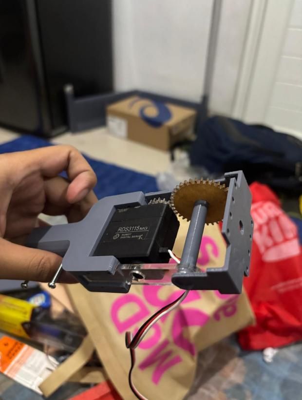
POSTER
The project on one page
Our UNS team, Samuel Louis Fajar Hasibuan, Ahmad Al Faruq and I, summarised the GMDC aircraft on this poster for the 49th Dies Natalis UNS. It covers the brief, mission profiles, weights, cabin, costs and the tilt mechanism as we had them at the time.
The numbers on it are the team’s design-stage values, as presented then. At the same event the team placed third in the Team-Based Project Competition.
Listed under Recognition on my About page →